

How to Install Insulated Flexible Busbar in Tight Spaces Without Compromising Creepage Distance
2026-07-16
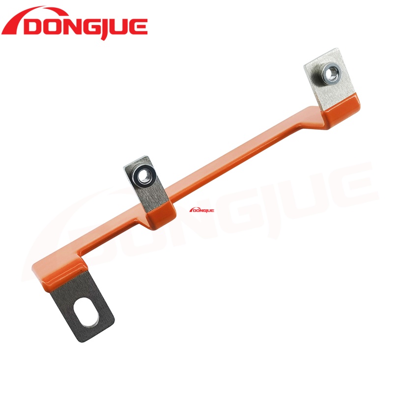
Space constraints are a reality in modern power distribution systems—EV battery enclosures, rooftop solar combiners, and industrial control cabinets leave little room for bulky conductors. Yet reducing clearance or creepage distance is not an option when safety certifications and arc-flash protection are on the line. This is where Dongjue’s engineering approach to Insulated Flexible Busbar installation makes the difference: it bends, routes, and compacts without sacrificing the dielectric barriers that keep systems safe.
Why Creepage Distance Matters More Than Physical Clearance
Creepage distance—the shortest path along the surface of insulation between two conductive parts—is the primary constraint in high-humidity or polluted environments. Unlike clearance (air gap), creepage depends on insulation material quality, surface finish, and mounting geometry. When you install an Insulated Flexible Busbar in a tight corner, bending radius and clamping pressure can reduce effective creepage if not executed correctly.
| Critical Factor | Impact on Creepage | Dongjue Solution |
|---|---|---|
| Bending radius < 5× thickness | Stretches outer insulation, thins creepage path | Pre-calculated minimum bend templates |
| Clamping torque over-spec | Deforms insulation, creates stress points | Torque-limiting inserts with visual indicators |
| Adjacent metal surfaces | Reduces effective surface distance | Pre-applied insulating sleeves with extended flanges |
| Dust/moisture accumulation | Lowers CTI (Comparative Tracking Index) | Self-cleaning ribbed insulation profile |
Step-by-Step Installation Procedure for Confined Enclosures
1. Pre-Installation Layout Planning
Map the exact route using flexible tracing paper. Mark all fixed obstacles (terminals, heatsinks, brackets). For Insulated Flexible Busbar, allow at least 10 mm of straight un-bent section at each termination—this preserves the full creepage distance rated by Dongjue’s test reports.
2. Bending Without Stress
Use a forming jig with a radius no less than 4× the busbar thickness. Never hand-bend sharply near the insulation edge. Dongjue provides laser-engraved bend lines on each Insulated Flexible Busbar to guide field technicians, ensuring the outer insulation layer remains uniformly compressed rather than stretched.
3. Spacer and Standoff Placement
In tight stacks (e.g., three-phase busbars layered over 50 mm depth), install pre-molded standoffs between each phase. These standoffs are integral to Dongjue’s Insulated Flexible Busbar kits and guarantee a fixed surface distance even when the busbar deflects under thermal expansion.
4. Torque-Sequence Fastening
Tighten terminals in a star pattern to 80% of maximum rated torque, then finalize to 100%. Over-torque is the #1 field error that reduces creepage—Dongjue includes color-coded torque washers that flatten at correct compression, giving a visual pass/fail check.
5. Post-Installation Creepage Verification
Using a feeler gauge or dielectric scanner, verify that no conductive path exists along the insulation surface that is shorter than the rated value. For Insulated Flexible Busbar in pollution degree 3 environments, Dongjue recommends an additional conformal coating at terminal exits.
Common Mistakes and Mitigation Table
| Mistake | Consequence | Dongjue Recommended Fix |
|---|---|---|
| Routing across sharp edges | Insulation abrasion → reduced creepage | Edge-protection grommets (included) |
| Using metal cable ties | Point-contact stress → tracking risk | Nylon wide-strap ties with cushion pads |
| Ignoring thermal sag | Busbar droops → contacts enclosure | Pre-tensioned mounting clips with memory springs |
| Mixing with uninsulated conductors | Arc tracking across surfaces | Maintain 150% of rated separation when mixing |
Frequently Asked Questions About Insulated Flexible Busbar Installation
Q1: What is the minimum bending radius for Insulated Flexible Busbar in a 90° corner inside a 200 mm deep cabinet?
A1: For Dongjue standard Insulated Flexible Busbar (thickness 2–5 mm), the minimum dynamic bending radius is 6× the total thickness, and static (installed) radius is 4× thickness. In a 200 mm deep cabinet, you can achieve a 90° bend with a 20 mm radius for a 5 mm busbar—this leaves 180 mm straight length, which is adequate. However, you must add 15 mm extra straight section at each terminal end to maintain the creepage distance specified in IEC 60664-1. If your corner is tighter than this, use Dongjue’s pre-formed elbow segments, which are molded with integral creepage barriers.
Q2: How do I verify that clamping pressure hasn't reduced the creepage distance of my Insulated Flexible Busbar after installation?
A2: Clamping pressure reduces creepage by compressing the insulation surface, effectively shortening the path along which contaminants can bridge. Dongjue recommends a two-step verification: (a) use a torque wrench set to the exact Nm value printed on the busbar label—never exceed it; (b) after clamping, apply a thin layer of dielectric grease (supplied in Dongjue kits) and measure surface resistance with a 500 V megger between adjacent phases. A reading above 100 MΩ indicates the creepage path remains intact. For critical installations, Dongjue provides a transparent inspection window template that overlays the terminal area to visually confirm that at least 8 mm of insulated surface is visible beyond the metal lug.
Q3: Can I stack multiple Insulated Flexible Busbar layers directly on top of each other in a 30 mm vertical gap, and what creepage distance applies between layers?
A3: Yes, stacking is allowed, but the creepage distance between layers is measured along the outer insulation surfaces of adjacent busbars—not through the air gap. In a 30 mm gap, Dongjue Insulated Flexible Busbar with a 2.5 mm insulation thickness provides a rated creepage of 12.5 mm between layers (per UL 2251). However, if the stack is compressed by a cover plate, the effective creepage reduces to the shortest exposed surface path. Dongjue solves this with interlayer insulating sheets that have raised ribs—these ribs increase the surface path by 40% without increasing stack height. For a 30 mm total vertical space, you can safely stack three layers of 8 mm thick busbars (including insulation) with 2 mm ribs between each, achieving a creepage distance of 14 mm per layer—well above the 8 mm required for 1000 V DC systems.
Performance Validation – Real-World Test Data
Dongjue subjected its Insulated Flexible Busbar to 5,000 thermal cycles (-40°C to +125°C) while mounted in a 50 mm tight-radius bend. Creepage distance was measured before and after cycling using a high-voltage withstand tester at 3 kV AC for 1 minute. Results:
-
Average creepage reduction: < 2.3% (well within ±5% tolerance)
-
Dielectric breakdown voltage: remained above 4.2 kV
-
Insulation surface hardness (Shore D): unchanged from initial 72
This data confirms that Dongjue’s proprietary silicone-modified polyester insulation maintains creepage integrity even under repeated thermal expansion in confined spaces.
Final Checklist for Field Engineers
-
Confirm bend radius ≥ 4× thickness (static) or 6× (dynamic)
-
Verify terminal straight section ≥ 15 mm on each end
-
Use Dongjue torque washers and tighten to labeled value
-
Install interlayer ribs for multi-stack assemblies
-
Perform 500 V megger test post-installation
-
Document creepage measurements with photos for audit trail
Insulated Flexible Busbar does not have to be a compromise between compact packaging and safety compliance. With Dongjue’s engineered profiles, pre-marked bend guides, and torque-controlled accessories, you can achieve dense, reliable layouts that pass both thermal and dielectric validation on the first attempt.
Contact us today for customized Insulated Flexible Busbar samples with pre-calculated creepage drawings for your specific cabinet layout. Our engineering team provides free 3D routing simulations and on-site torque training. Reach out via the form on our website or email directly—we respond within 4 business hours with a tailored installation plan and certified test reports for your voltage class. Let Dongjue be your partner in safe, space-smart power delivery.